Wednesday, March 26, 2008

Creating Multi-touch Software

Currently, homebrew multi-touch systems are mostly limited to Windows based systems. To make sure that multi-touch systems would be available to people on all platforms (and so I wouldn't have to muck about on a Windows box), I decided to create my multi-touch software for OS X. OS X was also my choice for multi-touch application development because of the frameworks available to developers, especially Core Animation. Core Animation is a framework for creating rich animations quickly and easily.

There are several components to a multi-touch software system. First, there must be a program to detect the blobs of light from the IR camera and relay the information about the touches to other programs. Then there must be a way to receive that touch information and interpret it into events such as a click, drag, pinch, or rotation.

I do not know much about image processing, so I was very glad to find there was a solution for OS X already out there. OpenTouch is an application written for Google Summer of Code 2007 by PawelSolyga that detects blobs of light from a camera input, and transmits the touch information by sending network messages to the localhost. Although OpenTouch isn't as mature as TouchLib, its Windows-only brother, it was far enough along that I used it.

Both OpenTouch and TouchLib send the touch data to other applications by sending Tangible User Interface Object (TUIO) network messages. TUIO is a protocol that is designed for transmitting the state of multi-touch systems. TUIO is built upon another protocol, Open Sound Control (OSC). While libraries for receiving TUIO messages are available in a few languages such as C++ or Java, there was not a solution for Cocoa applications. My first step was to build a library for receiving TUIO messages in Cocoa.

Because TUIO is built upon OSC, I looked for a library that could parse OSC messages. Unfortunately, I could not find one that would fill all my needs. WSOSC was a library that came close though. There were a few issues to work around (use NSData instead of NSString), but eventually I was able to use WSOSC to parse the OSC packets. When finished, my framework had the ability to parse TUIO messages and had a method to delegate the TUIOCursor objects it created to another application.

For the user interface I started by subclassing Core Animation's basic component, CALayer. I added methods to handle TUIOCursor objects, and automatically scale, rotate, or change position. I prototyped a few variants of this class to make objects that could contain pictures or video clips when dragged onto the screen from Finder. However, dragging on each individual file was an inconvenient way to get media onto my application. I needed a way to access media very quickly.

An image browser is an obvious application for multi-touch devices. However, I didn't want pictures of other people's kids all over my multi-touch table (not to mention that would break science fair rules). Instead, I decided to make an application to browse my favorite comics, xkcd. XKCD comics are released under the creative commons license, so I wouldn't need to worry about breaking copyright law either. As icing on the cake, there were transcriptions of most xkcd comics on OhNoRobot.com, which make searching for the comics very possible. I quickly whipped up a program in Revolution to download the comics and store their associated transcripts in an SQLite database. As an added feature, I also added the ability to tag the comics, so I could mark the comics that use profanity and choose not to show those for science fair. (This program is available for download for Windows and Mac if you want to try it out)

Once I had all the comics and transcripts, creating an application that could search for and display these comics in multi-touch enabled Core Animation layers was only a few solid nights of coding away.

Saturday, March 22, 2008

Making a Backlight

As I said before, the LCD screen on my MT table does not let off its own light. It needs to be backlit for the images to be seen. To date, I haven't found a very good way to backlight my table, but here is what I have tried so far.

For my first attempt, I tried to use the original backlight of the LCD monitor. The backlight from the monitor included two light sources, one on the left and one on the right, each on containing two extremely thin fluorescent bulbs. These two light sources shined into the sides of a piece of glass about 3/8" thick. This glass was frosted with a grid of ridges. I believe the backlight actually used FTIR to get a nice even light across the screen. As the light was shined inside the glass, the ridges on the back of the glass would disrupt it so the light came out of the glass evenly across the entire frame.

I hooked these lights and glass up to my table under the LCD panel using some mirror clips and plenty of duct tape. While this created a good backlight, it had a few problems. The first problem is that the frosted glass blurred my infrared blobs quite a bit. Also, having the light source above the camera introduced a lot of infrared light that the camera could see, which further obscured my blobs. The final problem was that the fluorescent bulbs were extremely thin, and many of them broke during my assembly. In the end, I removed this backlight setup.

My second try at a backlight was just a simple lightbulb installed at the bottom of the table, near my camera. This didn't look nearly as good as my first approach. I found the light from the light bulb was more yellow, causing discoloration of the image. The light was also not as bright, and less evenly distributed. The blob tracking was also adversely affected by this backlight. The lightbulb flooded the area with too much infrared light, even though I had used a fluorescent bulb, which gives off less heat and infrared than incandescent bulbs. This drowned out the blobs of light of my finger touches, and illuminated parts of the screen that caused extraneous blob detection.

My third try at a backlight is my current revision. I bought two under counter fluorescent bulbs and attached them at either side of the LCD panel, under the tabletop. This caused brighter illumination at the sides of the screen, because there was no diffuser like in the first backlight setup. I tried to fix this by attaching tin-foil reflectors to direct the light, but they didn't have a noticeable affect. The illumination is sufficient though. These bulbs also let off extra IR light, but by moving the camera closer to the LCD panel, so it doesn't pick up the light bulbs, I was able to negate a lot of this effect. I also covered anything that would reflect the light bulb's infrared light with black electrical tape, so they would not reflect light.
While my current backlight serves its functions, I believe that there are serious improvements to be made. I will continue working on that...

Friday, March 21, 2008

Creating the FTIR Frame

A central piece to my multi-touch table is the FTIR frame. This is simply a piece of acrylic with surrounded by IR LEDs shining into its sides. Finding suitable IR LEDs was a task. For good advice on which LEDs have been used successfully, search around and ask questions on the NUI Group forums.

My initial plan on wiring up the IR LEDs was to use take apart LED Christmas lights from the store, and replace the LEDs with IR LEDs. This way, I wouldn't need to deal with designing the circuit, and the wires would be nice and neat. While the plan sounded good in practice, it did not work out so well. I wasn't able to find any LED Christmas lights, despite the fact that it was only days after Christmas. Finally, I was able to get a hold of net-style lights. With a little modding, they were almost like regular string lights. I found a suitable IR LED with the same specs and ordered them from Mouser Electronics. In my haste though, I hadn't checked all the stats completely. The lights I ordered were not nearly bright enough, only 20 mW/sr instead of the recommended 100 mW/sr. They came anyway, and I paid for them. Perhaps someday I will find a use for them.

After doing more research, I found better LEDs. The LI521 IR LEDs from Mouser Electronics, with a radiant intensity of 80-120 mW/sr, sounded perfect. A little more expensive than my first order though. I went ahead and ordered 30 of them.

My acrylic I simply picked up from a local hardware store. It was 1/4" thick (or so it said, it is actually a bit thinner). I then cut the acrylic to be about an inch bigger than my LCD panel on every side. To maximize the amount of IR light that enters the acrylic, it is important that the sides of the acrylic are highly polished. This actually turned out to be one of the hardest parts of the multi-touch project, as sanding can take a lot of time. I used varying grits of sand paper, up to about 600, polished the sides with Brasso, and then ran the acrylic over a flame from my stove to get it very shiny. The edges needed to be shiny enough you could see colors that are on the other side of the acrylic. Once again, look on NUI Group for tips on how to get acrylic polished.

I wired up my LEDs by cutting thin strips of prototyping board, and then using wire wraps on the opposite side to connect the leads. I then covered the exposed wires with electrical tape. It wasn't a very clean-cut solution, but it worked, and it didn't take too long. If I were to do this again, I would print a circuit board and solder to attach the LEDs. Although I ordered 30 LEDs, I only wired up 20 of them. They would cover three sides of the acrylic, and be space about 1.5" apart.

To hold the strips of LEDs to the sides of the acrylic, I constructed a frame. The frame's sides were made of a three sided u-shaped metal thingy. Obviously, I have no idea what to call it, so from now on we shall call this metal phenomenon a foobar. Here is a picture of the part that I find so difficult to name:

The foobar is deep enough that the LEDs board can with within it. I constructed a frame out of the foobar so that the inside edge of the frame would be the same size as my acrylic. I then put the LED boards inside three sides of the frame, and put in the acrylic. I used plastic insulation strips to hold the acrylic at the right height for the LEDs to be shining directly into the edges. I used electrical tape to seal the gap between the acrylic and the edge of the foobar, so that IR light was not shining above and under the acrylic, otherwise the camera would see my fingers before they made contact with the acrylic.

With all of that done, I could attach it to the table! Here is an infrared picture of the FTIR frame on the MT table.

Thursday, March 20, 2008

Making My Table's Body

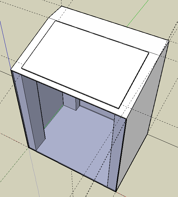
After my LCD screen was taken apart it was pretty much useless until I got a new way to mount it, so I created my table's body next. I figured my camera could see my whole screen area from about two feet away, so that is how big my table was going to be. To make sure I got all my measurements right I first made a model in Google SketchUp. It was my first time using said program, but it was extremely easy to use. Here is my first draft.

I really liked this first design, but it wasn't very realistic. First, it wasn't two feet tall. Second, the table would need walls, so the backlight wouldn't be shining all over the place. Third, I don't own a Mac Mini.
So I went back to the drawing board. This time I didn't do all the fancy textures though, as they were really starting to tax my poor little MacBook by the end of the first model. The second model is not nearly as cool looking, but I was able to incorporate the slanted tabletop. I like that. Here is the second (and final) try:

First I made the tabletop. It was made out of a piece of leftover PVC from my brother's store, Signs By Tomorrow. We cut out a hole 1/8" smaller than my LCD panel. Then I used a Dremmel to carve out a little ledge for my LCD panel to sit on flush with the table's surface. To make the little crook in the tabletop we sawed a short line about 3/4 of the way through the panel and then bent it.
I have never done any woodworking (besides making a few things out of balsa wood for the sole purpose of crushing them) so I had my brother-in-law help me build the rest. I used 2x4's (which are not really 2" x 4" !) as my legs, then I made walls using some b-board my family had leftover from a bathroom remodeling. It went really smoothly. All the measurements were taken from the Google SketchUp model so everything fit together really great. I am sorry, but I didn't have my camera there as I constructed my table, so I have no pictures here.

Attaching the LCD panel was really easy once I had the table done. I simply placed my LCD panel in the little groove I had created for it, then ran the wires down below and attached the circuit board and power supply to the underside of the tabletop. Here is a picture of the inside of my table, looking up. Those wires are from the original backlight, which I tried to use but failed.

Labels: ,

Taking Apart My LCD Monitor

It was one of the scariest moments of my life, but it had to be done. It takes some guts to take apart a 19" LCD screen that cost $120, but if you keep the multi-touch table in mind, it is worth it. I didn't want to take apart my screen only to find out it doesn't work, so I did a lot of research. A great place to check if your screen will work or not is LumenLab. Make sure your model doesn't have FCC issues, which means there are non-movable components that block the LCD panel. My model was the Acer AL1916W, which worked perfectly.

What you are trying to do here is strip down the monitor until you are left with the LCD panel and the electronics. The LCD panel is just a thin plate of (glass, plastic?) with some ribbon wires attached to the top. The pixels on the LCD panel can turn different colors but are mostly transparent, especially to IR light. So lets get started!
My monitor:

After taking all the screws out I could, it still wasn't coming apart. I used a screwdriver and slowly pried it apart, breaking the little plastic snaps all around it. This was the point of no return and came surprisingly early for this project.

Here is the back of the monitor with the plastic case taken off:
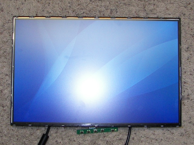
Here is the front of the monitor. It is actually on right now. The little green dangly thing at the bottom is the controller for adjusting brightness etc. If you look closely you can also see the little gold strips at the top. These are the ribbon wires that are connecting the LCD panel to everything else.

Here is the LCD monitor with the panel lifted away from the backlight.
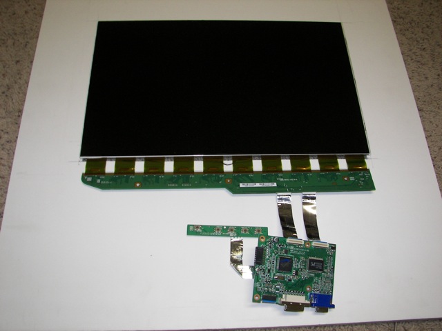
I disconnected everything I could from the actual LCD panel (except for the controller), including the power supply.

After you take everything apart, you will be left with a lot of extra parts. The sheets of foggy papers are diffusers. For a nice looking picture, you will need to put these between your LCD screen and the backlight to make the light even. I also kept the lights from the backlight, to see if I could use them myself.

Tips: Make sure you don't wear socks or do your disassembly on carpet. In short, keep everything static-free. I didn't, and now I have a few lines of discolored pixels.
Make sure everything is unplugged as you take everything apart. I only plugged it in for a second to reassure myself that nothing was broken yet. Watch out for capacitors too, as they may still be carrying a charge.
When you plug in your monitor to see if it still works, and it doesn't. Don't panic until you try another outlet. The one you are using is dead.

Labels: , ,

Modding an Infrared Camera

To sense the infrared light coming from my FTIR frame I would need a camera that could only see infrared. As it turns out, the sensor in most web cameras (a CMOS sensor) is sensitive to infrared light. However, most camera manufacturers place a filter within the camera to block the infrared light, so that images being made are closer to what the human eye sees. After all, when have you seen a remote control let off a bright beam of light every time you changed the channel, or drank clear Coca-Cola? To make an infrared camera, I simply had to replace the infrared block filter, with a filter that blocks everything except infrared light. A cheap way to do this is to use an exposed photonegative.

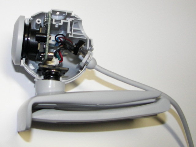
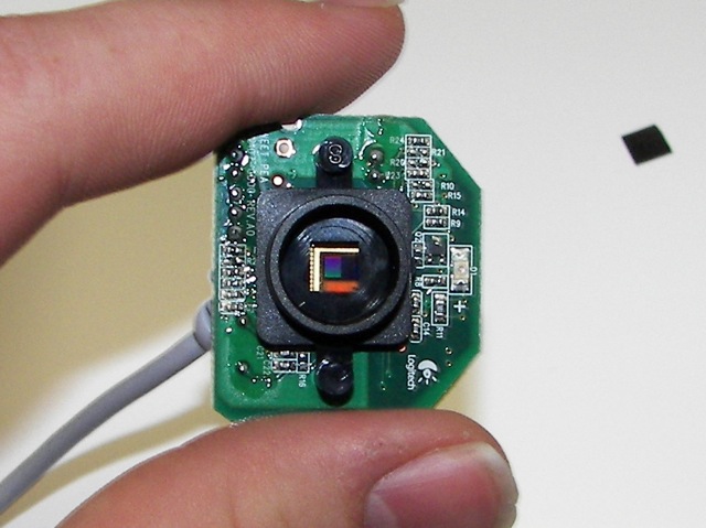
I purchased the cheapest camera I could find at Radio Shack. A $30 Logitech Quickcam Chat. Then I removed anything that looked remotely removable, and unscrewed everything else. here is the inside of the camera:

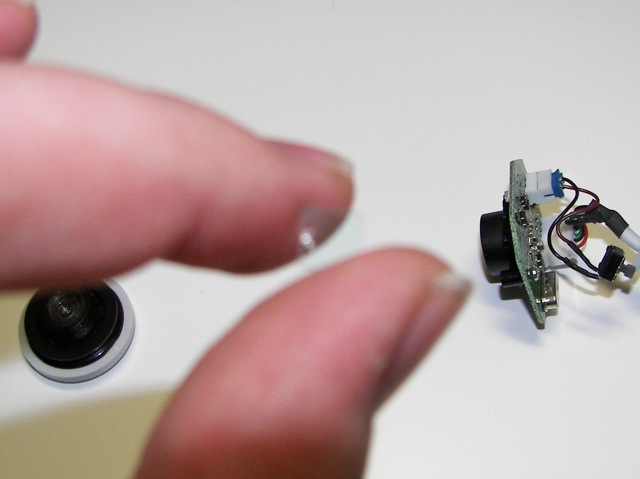
The infrared sensor was found by unscrewing the lens. It is a small piece of glass that has a red-ish tint to it in the light. It cracked a bit coming out, but that is okay, as it is no longer needed.

The inside of the camera sensor:

My best try at taking a picture of the IR filter:


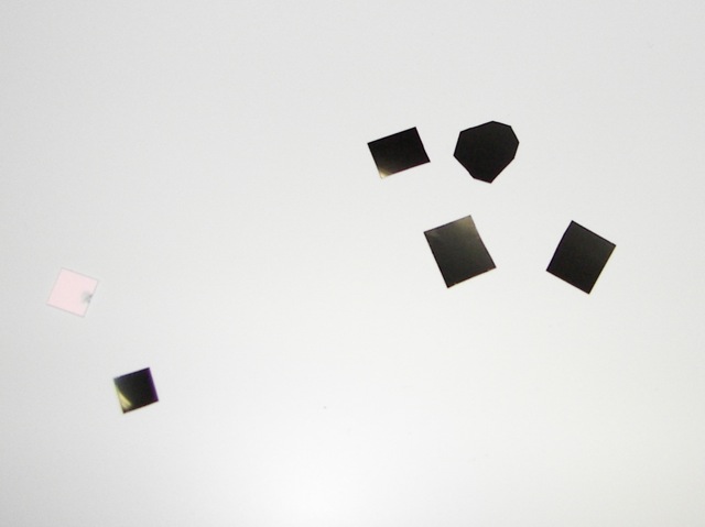
Once the IR filter was removed, I put in the exposed photo negatives. The more you put in, the blurrier your image is going to be. However, they aren't perfect filters and will still let some visible light through, especially if it is bright. I found that three little layers worked fine.

Here are the filters I put in. You can also see the IR filter to the left:


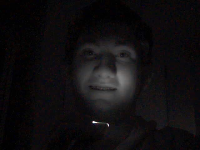
Now I put the camera back together and tested it out. It wasn't compatible with OS X natively, but with the help of the driver from http://webcam-osx.sourceforge.net/ it worked just fine. If you are using OS X, make sure your camera runs on OS X before you take it apart, as any disassembly tends to void most warranties. It is really fun to play with the camera.
You can use a remote control as a flashlight.

Any really hot things, like my space heater become light sources.

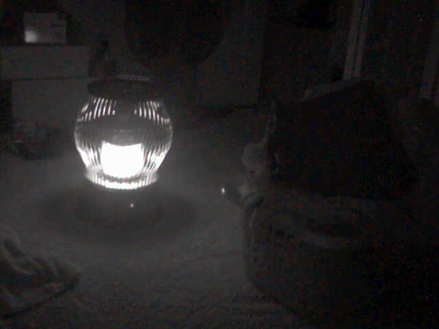
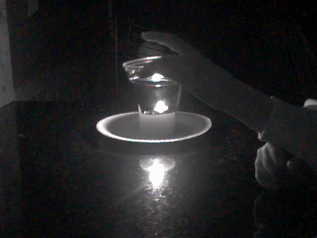
Coca-cola even looks like water with IR (that is a candle behind the cup of Coke, by the way).


*Note, these IR pictures actually weren't taken with this camera. I got a different camera later on and took these pictures with it.

Labels: , ,

Planning My Multitouch Setup

As it turns out, not all multi-touch surfaces are created equally. There were many decisions that had to be made before getting started. Here is what I decided on.

Touch Sensing
For homebrew multi-touch systems, there are basically two different ways to detect your touches. I will briefly go over each. The first is direct illumination, or DI. Basically, DI uses an infrared source to illuminate the touch surface and an infrared camera to see what is on the touch surface. This approach allows you to see anything on the touch surface, whether it be fingers, a paintbrush, or fiducials.

The other method uses Frustrated Total Internal Reflection, or FTIR. The theory is that when infrared light is shined inside the edge of a material such as glass or acrylic, it will be reflect internally to the other end of the material, never escaping. However, when a finger touches this material, it "frustrates" the internal reflection, and causes the infrared light to escape through the surface of the material. An infrared camera then tracks this on the opposite side of the material. Unfortunately, this method does not allow much else than fingers from being tracked.
The method I chose was FTIR. To me, it looked more stable than DI, not needing as much calibration and not being as susceptible to outside interference.

Display
One of the coolest parts of multi-touch is the illusion it creates of manipulating virtual objects as if they were on the table in front of you. This requires the touch surface, and the display to be on top of each other. Much easier said than done. One method is to use a projector to shine the image on your touch surface. Projectors aren't cheap though, and I didn't have any spares lying around.

I decided to go with a more affordable method, using an LCD monitor. I know what you are thinking. "But you have to track the infrared blobs through the display, and LCD monitors are very much opaque." That is exactly what I thought. As it turns out, the actual LCD matrix in an LCD monitor is clear. It is just a piece of glass(?) that can color itself. Then, behind this is a backlight which allows you to see the image. By ripping apart an LCD monitor (gulp) you can take out the LCD matrix and mount it on your multi-touch table. You just have to figure out your own way to backlight it.

Multi-touch Surface
The final major design consideration is how you are going to display your multi-touch surface. Because I will only be using a 19" display, a wall display wouldn't be very impressive. Also, this being a science fair project it can't be overly large or I won't be able to fit it. My goal is to enclose it all in a box, about 2" on each side.

So that is my planned multi-touch table. I will post more progress, and some photos soon.

Labels: , , ,

Making a Multi-touch Table

After seeing some of the awesome multi-touch demonstrations on Youtube, who wouldn't want their own multi-touch table? The only thing that stopped me from going out and buying my own immediately after seeing Jeff Han manipulate his vacation photos as if they were scattered cards was the price tag. A multi-touch display from Perceptive Pixel costs in the ballpark of $100k. Microsoft's version of multi-touch, dubbed the Microsoft Surface is estimated to be between $5,000 and $10,000. And those are assuming that you can find a model ready to be sold. I don't know about you, but as a high school student, I don't have that sort of pocket cash.

Luckily, there are already online communities scheming plans to bring multi-touch to their houses for a reasonable amount of money. I decided that I would build my own. Here I will document my progress, and hopefully help someone else bring this awesome technology home. Also, a great place to look for information on building your own multi-touch table is www.NUIGroup.com. They have been invaluable to me along the way. Seriously, some very awesome people are there.

Labels: